Story
So I have arrived at the Mexican farm that the drought has effected
the irrigation of water. The first thing is to gather all the workers
because my plans and the effort are going to need all of us to work
together. The first thing I need to know is our supply list. I can move
the water, but long pipe would aid our efforts. I especially need to
know what equipment is contained in the greenhouse and metal barn.
I find the broken tractor. It would help move the 1,500 gallon oil
tank filled with water, but I think we will manage to move the tank
with the donkeys and the wagon. The tractor would be difficult to fix
without parts. However it is not out of the option later to fix it because
I know a little about small engines. However, the first major problem
we face is filling the 1,500 tank.
Chicko, the farmers son, has informed me that there may be limited
pipe or hose in the greenhouse. Enrique, the old farmer, is desperate
to hear my plan, but as I can read his body language is impatient. So
this idea must sell.
I explain to the entire family that we do have ample amount of time
before the plants die due the sunlight. So with this time we must create
a solution that will last weeks, because there is no way to know how
long the drought will be. Right now the only water supply is the pond,
but I explain it may be necessary for a well to be dug. Though, today
we concentrate our efforts on moving the water from the pond.
I decide to divide the work. Sandra, the daughter, is the smallest
but is still old enough to help me with repairing the tractor and filling
the tank. The wife, Enrique, and his son will move be the labors moving
the water to the crops.
I tell them to unravel the 4 mil clear plastic near the end of the
pond. Cut the plastic of lengths of around 5 ft. Cover it with about
and inch of dirt. Wet the soil throughly with the buckets until the
dirt is saturated. Cover with the 4 mil black plastic. Now roll the
plastic inward over a 4 inch piece of pipe (The pipe is not necessary
but makes it easier to move, turn and carry.) Now using 2 men on each
side load it into the cart which will be pulled by the 2 donkeys. It
will the be hauled to the rows of crops. The black plastic will be removed
and saved for another load. The clear plastic will then be turned over.
(The sections are small enough were it should be able to be flipped.
You could only use the clear plastic and unravel it with the dirt facing
down and the plastic facing up.) Finally some holes will be punched
in the clear plastic.
This is the easiest, current way to distribute water until we can fill
the tank and empty it. This will distribute water evenly through the
soil and the plastic should keep moister in if it does evaporate. This
is only temporary. We want to keep water off the plants leaves so they
don’t “burn out” in the intense sun.
I explain to the family my week long solution that will last as long
as the pond is full, but does require a lot of work. That isn’t
a problem because this family knows the meaning of hard work and this
crop is very important to them and their lifestyle.
We have no choice but to use the 1,500 gallon tank. Moving it should
not be a problem it can be put into the wagon and pulled by the car
or donkeys if the car isn’t available. If the wagon doesn’t
work we can build our own cart from pipe or the frames of the other
farm equipment. The 3 wood barrels are no good for transporting water,
but could be used as wheels for the improvised cart. The tractor also
has tires we can use.
That was the easy part because for the barrel to be effective there
has to be a way to relatively fill and empty it fast. The two donkeys
are strong enough to pull the tank on wheels or in the cart. I inform
the family I have many solutions to the problem because some first tries
may not work. I first thought of syphoning the water but that is too
slow. I also considered a water auger that looks like a drill bit and
lifts the water up as it turns. But that isn’t practical to build
and would not be able to remove water from the tank. My solution is
to use a water pump from the materials we have.
This water pump will be built in several ways. The car and possibly
the large farm tractor have a water pump. This is because the engines
are cool by liquid (anti freeze) and not air. If I could connect a hose
to the inlet and outlet of the water pump that is already assembled
and very efficient, all that would need to be done is to start the engine
and the pump would do the rest. Of course the hoses would need to be
flushed for a while, but if this works we will be able to water the
crops completely by the end of the day.
The first continency plan is that if the car or tractors water pump
fell is to construct an improvised pump system using hoses and pipes
from the greenhouse or farm equipment. Using what I know about pumps
and their physics I know of a few ways to design a pump, but its fabrication
is going to take awhile from the equipment we are working with. There
is no time for “product research” so I will either invent
something ingenious or waste time “creating a south pointing chariot.”
Pumps work on pressure and vacuums combined with a little mechanical
force. I want to build a pump that has a little rotating propellor that
forces air or water out of the flowing end. Unfortunately I have no
way of containing the water in a water tight canister. (Imagine how
an airbrush works.) So my design relies on a vacuum. I am going to take
a flexible hose and cut a piece of that hose to fit into the original
and form a piston. (Imagine a syringe.) That pipe will be pulled in
and out of the main pipe by a rod attached to gears turned by an engine
from one of the farm equipment (or either the car or broken tractor).
There will be a simple value that is closed on the vacuum stroke and
open on the compression stroke. This will be on the end of the hose
and the rod will be small enough that it still fits easily into the
tank.
We are building the improvised water pump when Sandra asks, “Senor
Snyder this is fun, but is it going to save the plants.”
I tell little Sandra, “a scientist once said: Don’t be afraid
to kiss frogs.” I continue, “that is why I have several
plans because some might not work, but with every one that doesn’t
work you learn something. It is that “little something”
that just might help us reach a solution. It helps us “narrow
down” which frogs when kissed will turn into a Prince or Princess.”
“Senor Snyder,” Sandra adds. “I don’t want to
kiss frogs. I just want to water the crops.”
“It is just an expression,” I assure her. “Each frog
represents our proposed solutions. Kissing a frog wouldn’t be
so bad if it turned into a Prince now would it? This is where the job
becomes harder than the physical labor. Sometimes the right idea in
the right time is harder than any physical labor ever could be. Sometimes
it’s easy, but usually finding the right plan is what determines
success. I think we have some good ideas. Do you have any ideas Sandra?’
“Why don’t we drill a well Senor Snyder?”
“Not a bad idea. Unfortunately I don’t think we have the
equipment. But if the drought continues I think we’ll need a dowser
or geologist. But that is a great idea kid.”
“Senor Snyder I think you plans are going to work. We’ve
found a Prince on the first frog.”
“Let’s get back to work kid and prove you right.”
Later Chicko return from doing the grunt work. “Senor Snyder we
have laid the wet soil covered by plastic. What have you accomplished?”
Sandra says, “we have built a few pumps and kissed some frogs.”
“Have a Coke Chicko,” I say as I through him a bottle. He
turns on the pump and it doesn’t work.
“We have been working hard all afternoon and this is all you guys
did it doesn’t even work. We never should have listen to you stranger.”
Sandra interrupts, “It will work. Tell him Senor Snyder.”
I grab the empty Coke bottle and ask Chicko, “What is this.”
He replies, “It’s a plastic bottle.”
“That is right I say but I prefer to call it a funnel. A funnel
that placed on the four inch, inlet hose will solve all the pumps efficiency
problems.”
They watch as I cut the bottle with a pocket knife and insert a piece
of cut screen in the pipe and connect the Coke bottle funnel. I give
Chicko the honor of starting the pump. He waits impatiently for a minute.
“It works amigo! It works!”
Design Notes
Before explaining the design of my “water pump” I want
to explain some of the design difficulties. It is easy enough to design
a pump. There are pumps in every day items. The challenge is the improvising
used to make one in the field. There is no machine shop to turn out
custom parts. Springs, valves, and gears that don’t break the
seal of the pump are all design challenges. I chose a design that could
be made in around 3 hours once the materials were collected. It isn’t
the most efficient pump. Also I have only tested it in theory. I tried
to rely on my own knowledge for this MakeShift 04 solution because that
is how it is in the field. You don’t have the library or Internet.
But although my design may need some tweaking, I feel it is a good solution
to pumping the water into the oil tank.
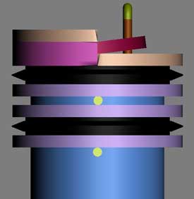
The design is simple but required some thought. You find a hose or
plastic pipe and place another slightly smaller hose in it. The smaller
hose can be cut into 1/4 ths and then clamped together with a metal
ring so that it is adaptable to many different sizes of pipe. (In the
drawing a smaller hose of 1" radius is used to get general proportions.)
Simply stated an over all description of the pump is the following.
It is a piston like device with a valve to release the water. It is
similar to a small gas engine piston. A subject that I have recently
studied. Here is how it works. The smaller hose is inserted into the
larger hose. Small metal cylinders are inserted into holes in the small
hose and held in place by two bolts along the inside of the hose. The
very top bar is the place in which the improvised valve rotates. This
top bar is not in holes in the hose, instead it has a bend piece of
metal connecting it to the main bar below it. The valve is connected
to the top bar by wire wound around the bar. If holes are necessary
to put in the valve sealant can be used to make it water tight.
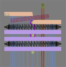
Continued: the valve is opened and closed by a bar connected to a gear
system that moves the smaller hose back and forth. The valve will open
on the inward stroke and close to form a vacuum seal on the downstroke.
This inward / outward motion is tricky to create, but is possible to
improvise. (That will be discussed latter.) This seal is how the pump
works similar to how a syringe would. But it also has a the valve opening
to complete its motion. The same bar that pulls the small hose back
and forth is the same part that opens and closes the valve. There are
measured slits in the small hose to let the bar move without moving
the hose and at the same time opening the valve.
Some notes on the valve are that there are seals on the top and on
the bottom. The seals are opposite the way the valve rotates. They are
split halfway in the picture. This only allows for the valve to open
a small amount. To improve this the valve could be slanted or the valve
could be in the shape of a “z”. The easiest solution would
be to make the top seal less than half of the bottom. This would give
the valve more room to rotate.
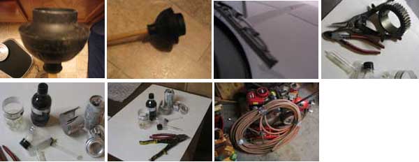
A key part to the piston is the rubber seals that keep the piston water
tight. To improvise these rubber from hoses, cut pieces from a plunger,
or the most preferred method of windshield wipers. Malleable metal may
also be shaped. (I originally thought of a soda can, but other than
the bottom the metal is too thin.) All of this contraption is held together
with a long pieces of thin metal clamping together all the parts together.
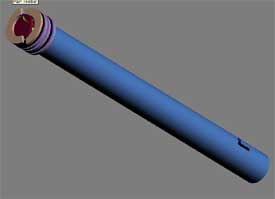
In the drawing the small hose (piston) is inside the large hose that
connects to the water source. This is only one combination. If pipe
joints are available a joint with 2 outlets could be used. One hole
containing the piston and the other an outlet for the water. A improvised
valve could be made to cover the outlet to improve the pumps power.
I should also mention that a screen and funnel shaped piece such as
a cut soda bottle be placed in the inlet hose or pipe.
The back and forth motion must be addressed. There are several ways
to improvise this: electric motor that turns both ways, gear cut in
half, turning gear teeth, a chain that alternates gears like a bike,
or a transmission similar to a car. Each of these could be explored
in depth, but are a MakeShift solution themselves.
Note on Back and Forth Motion
The modified gear drawing is just to show that producing an equal
back and forth motion is possible. Cutting the teeth of a gear in an
arc length less that 180 degrees is a simple, quick, improvised solution.
The only problem is that it takes a large size gear. This gear could
be found on a car or possibly a tractor. But in this drawing to move
the piston 14 inches a gear of a minium 10.7 inch diameter would be
needed.
Of course there are other methods I just want to show that the back
and forth motion is possible. It is a topic to tinker with and research
what designs are already available. It would take me quite some time
to draw out the best solution. Designs often lead to more designs especially
when a problem occurs. I have mentioned other ways to produce this back
and forth motion earlier in the write up.
Hopefully my description is clear. The pictures should explain everything
after studying them a while. The piston drawing can be viewed in 3D
Studio Max. It’s proportions are correct. It helped me to visualize
the design better drawing in 3D.
Oh and .... May the Creative Force be with You, the reader! |